

Many times, through the years, the impact of an incorrect jet/wire ratio has come up. The following article is a refresher on this topic.
The “jet/wire ratio” (J/W) is the ratio of the jet velocity to that of the forming fabric at the point of contact in the forming zone. Some mills use the velocity difference between the two, called “rush” or “drag,” depending on whether the jet is faster or slower.
J/W is one of the key parameters defining paper properties such as MD/CD tensile and TSI (tensile stiffness index) ratio, compressive strength (RCT or SCT), moisture curl, and formation. This is due to the shear produced between the suspension and the forming fabric, causing more or less fiber alignment (anisotropy), not only overall but to a different extent top-bottom (differential anisotropy). Operating at a non-optimal J/W results in not realizing the full quality potential of the furnish and in possible converting and end-user issues, including variability.
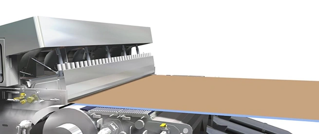 Image Source: Valmet
Jet velocity is calculated based on the following typical equation: Vj = √(2gh),
where g is acceleration (32.19 ft/s² or 9.81 m/s²), and h is headbox pressure (also called total head) in feet or meters of water column. By rearranging this equation, one gets:
h = Vj²/2g. As J/W = Vj/Vw, the equation becomes h = (J/W * Vw)² / 2g.
Total head must be corrected for the elevation difference between the transmitter located in the headbox nozzle and the contact point in the forming zone. For example, at 3000 ft/min (914.4 m/min), the expected total head is 466.0 in. H₂O or 116.1 kPa at a J/W of 1.000 and no elevation correction. If the transmitter centerline is 2 inches above the forming zone, the expected total head becomes 464.0 in. H₂O, or 115.6 kPa. Operating at a J/W of 0.975 reduces the jet velocity to 2925 ft/min (2.5% or 75 ft/min drag), and the total head to 441.0 in. H₂O, or 109.8 kPa, at the same fabric speed and transmitter elevation.
These calculations normally reside in the Quality Control System (QCS), which receives the fabric speed or calculates it from a tachometer input located on a major roll (normally the couch or forward drive roll) whose diameter is accurately known. The total head required to meet the J/W becomes the setpoint for the total head control loop.
The total head is measured by a special pressure transmitter located in the headbox nozzle, downstream of the turbulence generator. The headbox supplier normally provides a more accurate equation than the typical one shown above, specific to the headbox, which comprises correction factors and is entered in the QCS at headbox installation. Best practices today feature the use of two transmitters (one at the tending side and one at the drive side)—one for control and the other for monitoring—both displayed on the operator screen. A selector allows choosing which unit is used for control. It is also recommended to calculate the difference between the two outputs and compare this figure to a KPI, normally about 2–3 inches of water, so that action can be taken (transmitter switch on the run) followed by the replacement or recalibration on the next shutdown. Ensuring a reliable J/W readout is a must to achieve the best quality!
Operations must also determine the J/W ratio that provides the best quality results. This is done by running a test called a Jet/Wire ratio trial, during which—under stable conditions of furnish, basis weight, speed, and headbox consistency—only the J/W will be intentionally changed, in a range of about 0.95–1.05, in 0.01 increments. This ensures that the “rush” and “drag” areas are properly covered, including the “null” point (1.000). Paper is sampled full width at each point and key properties measured, either manually or using an automated testing line if available. Tensile or TSI ratio is used to identify the null point, where they will show their minimum value (see Figure 1). Note that running the trial at a fixed slice opening will result in a slight consistency change (of a few percent) normally considered small enough to be ignored.
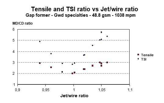 Figure 1.
It is not uncommon to find the null point at a J/W different from 1.000 due to calibration or calculation errors. Short term, such a situation is not of great concern as long as the optimal J/W is established. However, some time should be spent trying to identify the error(s) to properly establish and follow KPIs in the future.
Depending on the mill situation, the J/W ratio trial can be run over a number of reels, sampling at turn-up, or in a short succession of changes within a reel and suitably flagging the latter and slabbing off the transition paper to access the trial zones. A “poor man’s” way of following changes in J/W during such a trial is to monitor the width of the sheet at the reel either manually or with the QCS, as it will progressively increase as the J/W nears the null point. Such width data should be considered qualitative and complementary, and sheet orientation should be calculated based on TSI or tensile ratio. This is because other factors are involved in sheet width, namely moisture and draws.
For best results, J/W KPI values should be stated to the 3rd digit, for example, 1.025. Optimum quality requiring a “square” sheet (least orientation) will normally be found near the null point, but not necessarily at the null point. The trial data will indicate what J/W produces the best quality level. Note that this optimum J/W may not be the same for each machine speed. Different grades (e.g., basis weights), made at different speeds, may require slightly different optimum J/W, and hence different KPIs for operators. Additionally, another reason to explore the “rush” and “drag” sides is that the resulting quality may differ at the same distance from the null point, and it may be advantageous to use one side or the other— “rush” or “drag.”
Common J/W errors include transmitter drift and incorrect calculation in the QCS, including conversion factors. Note that J/W is never to be used as a tool to correct headbox consistency! Consistency must be changed by slice opening, with the headbox being run under total head control.
I hope this helps!
About the Author
 Jacques Perrault
Chemical engineer, he graduated from Polytechnique in 1976 and has worked for various paper companies (CIP, Domtar, Alliance forest Products, Bowater, Cascades) on the optimization and troubleshooting of papermaking processes of different grades (newsprint, groundwood specialties, fine papers and containerboard).
He also worked for Black Clawson, a paper machine builder, on the Top Flyte program and was directly involved with new machine projects as technical manager, such as Dolbeau PM5, Donnacona PM4 and the conversion of the Bear Island newsprint machine to containerboard. Jacques supported other start-ups such as those of Domtar Windsor PM7 and 8 and that of Greenpac, and prepared for Hydro-Québec a practical guide to energy conservation in papermaking.
Jacques was involved with the Canadian Pulp & Paper Association throughout his career and a member of OIQ, PAPTAC, TAPPI and IASPM. He holds a patent on an instrument to measure paper waviness, and was presented with the PAPTAC C. Howard Smith and Jasper Mardon awards.